Thursday, December 27, 2012

A Long Overdue Update! The engine runs!

The engine is finally in an operational state, and doing very well. When did this happen? Well...

School and life have recently distracted me from my efforts to share my projects, but work on the gas turbine has continued.


I haven't been documenting the progress as closely as in earlier posts, so I'll do my best to pick up where I left off.

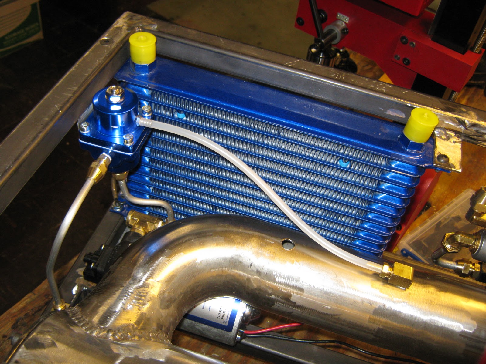
To start with, the evap system is finished. Here are some pics of the completed assembly:


The flame tube, also known as a combustor liner (the long tube within the combustor, which fits over the top ~3/4" of the evaporator plenum) has also been completed. This element serves a simple, yet crucial purpose. It allows for a uniform flow of air into the plume of burning fuel. This stabilizes the flamefront (prevents inlet air from "blowing out" the flame in the combustor), and controlls the heating of the air moving through.

Many belive that these engines run only by virtue of the expanding gasses resulting from combustion.

In fact, only a small percentage of the air moving through the engine is used to burn fuel. The majority of the air is simply a working fluid, which is heated by the combustion process at a constant pressure, and increases in volume (which translates in an increase in velocity, and inertia)

If you don't belive me, take a look at the T98-NT-XX gas turbine built by the guys at Nye Thermocynamics Corp.

Its a gas turbine which runs on wood!


The holes are all of a very specific placement and diameter, in order to provide the optimal mixing flow speed through each section. The holes on botom (towards the front end of the combustor) compose the primary mixing section. These small holes minimize turbulent flow of air into the flame tube, while maximizing the volume of air flowing, in order to burn all of the fuel spilling out of the evaporator. The medium-sized holes in the middle of the tube comprise the secondary mixing section. These are of a larger size, and total flow area, in order to provide a moderately turbulent flame/air mixing zone. This supports more complete combustion, and heating of the air flowing through. The tertiary zone (the large holes towards the top) provide a path for the rest of the air moving through the combustor to cool combustion gasses, and enter the turbine.

The last major component I've completed is the jet nozzle.


This nozzle gradually reduces the turbine outlet diameter from 5" to 3", inducing an increase in exhaust gas velocity, for the same mass flow leaving the exhaust.

The engine is running, but what good is that? Keep posted for more developments!

Wednesday, January 25, 2012

Evap System Nears Completion

Work on the evap "can" continues nicely, although with the hickups of a broken mill and a short lack of welding gas. I've also invested in a new Horizontal Bandsaw! It has already proven it's worth, and I'm very happy with what it allows me to do.
    

Since, the mill has been fixed and gas has been gotten. Now its time to proceede with the construction of the evap system. I cut off a 3" section of 4" diameter stainless tubing from the excess on the end of the combustor, then cut , pinched, welded, and ground the piece untill it fit snugly inside the 4" flametube. I then welded it to the evap "can" base.

Folowing this, I drilled a 1" hole in the center of the "twin" plate to the one that is the base of the evap can. I cut another 2" circle as the base of the evap tree, and proceeded to drill 3 holes which will hold the evap "tree" onto the "can".  I then drilled a large 1" hole in the mount for the "tree".

To make the tree, I used a hole-saw to profile the ends of three 3/4" tubes (the branches) to fit a 1" main "trunk", then cut each "branch" at 45* so they would make a nice "J" turn twoards the front of the combustor.

I'm using two different fuel injectors for two different fuels. The first and foremost is the main fuel injector. This is a cone-pattern spray nozzle that will evenly cover the sides of the evap tubes with a spray of diesel to be vaporized and burnt during normal operation.
The second injector is for the propane starting fuel. The evaporative fuel system can't be used unless the evap tubes are hot eanough to vaporize liquid fuel. To heat them up for starting, I'll use a small propane "pilot" injector. This is just a standard brass hex-plug you'd find in the plumbing isle, into the sides of which I've drilled some small holes. The radial hole pattern will be better for heating than injecting propane straight down the length of the combustor.


More to come soon!


Saturday, May 28, 2011

The Begining of an Evaporative Fuel System

A liquid-fueled DIY gas turbine poses one fundamental challenge. Diesel fuel (this engine's fuel), Kerosene, Jet-A, etc. all need to take the form of an atomized vapor before being burned. In commercial aircraft, this atomization is achieved via high-pressure (~1000 psi) fuel injection system, and a special injector.
Unfortunately, a 1000 psi fuel pump would cost a pretty penny which I don't have, and gobble up lots of onboard power, which I won't have.
The solution to this conundrum lies in evaporation. The fuel will dribble out of a nozzle into a "tree" of 3 small stainless steel tubes, which are heated by the combustor. The diesel or kerosene fuel vaporizes quickly upon contact with the hot metal, and the resulting vapor burns easily in the combustor.
I plan to incorporate the "evap" system into the flame tube (the tube somewhat resembling Swiss-cheese inside the combustor which allows the fuel to burn with an even supply of air). For this, I will start with a 3.84" diameter, 3 inch tall "can" with a large hole in the side. This will mount to the end plate of the combustor, feed air to the evap "tree", and support the flame tube, which will fit snugly around it.
 With much cussing and a little blood, I milled two 3.84" stainless circles on my undersized rotary table, then drilled 6 holes to the front of which nuts will be welded. This is the "bottom" of the evap can, which will fit over the 2 fuel injectors (starting and main fuel).
 Here drilling corresponding holes in the combustor end plate.
The finished ring. I also milled a full circle of the same diameter, which will be used as the top of the can.
Heres the end plate installed back on the engine. Looking a little more complex :)
And last but not least, its my pleasure to welcome the newest member of the Feathers workbench, a harbor freight belt sander :). Should get some nice use out of this piece.

Check back soon!

Tuesday, May 3, 2011

Time-Lapse video of the build so far.

I've been making an effort to document this project as well as I can, and have been grabbing snippits of video here and there. While you look at this one, feel free to check out some of my other youtube videos.
Now lets see if I can imbed this for the life of me...

Stay thirsty my friends!

Monday, April 25, 2011

The Oil Cooler (or whats left after "Austin" happened to it)

The 15 row oil cooler I purchased for a thrifty $50 presented me with a problem. The fittings were, as expected, size 10 AN (Army-Navy) performance automotive fittings (they originated in the military, so they cost a pretty penny). Nearly worthless to me, because I'm using standard plumbing sizes and common 45* flared tubing connections instead of AN's weird sizes and awkward 37* flares (even though AN looks WAY cooler). Reason(s) being, AN fittings are ridiculously expensive, and you can't buy them at the hardware store.
As fate would have it, the inside diameters of these giant AN fittings were the perfect starting size for my 1/4" NPT (National Pipe Thread) tap. For the sake of space, I beheaded both the fittings, then tapped them out.
I then went ahead and plumbed an aluminum line from the oil filter to the forward side of the oil cooler. Not too bad.

Tune in next time.

The Re-birth of an Oil System...

I'm sick today, and had some time to get back to the engine. My first oil pump, a Fimco Gold series multi-diaphragm pump, was an agricultural pump, and simply wouldn't supply the viscous oil at any amount of pressure. I have a sneaking suspicion that this complete lack of oil pressure led to the death of my last attempt at building a gas turbine. As not to repeat the mistake, I've purchased a gear-type oil scavenging pump, meant to return oil from a low-mounted turbocharger, or to operate a separate oil system for the turbocharger. It's allegedly rated 2.5 GPM at 60 PSI for oil.
That is, of course, for a car. We'll see how it does.
Here's the engine with the new pump all mounted and plumbed up. I've replaced the pump feed line with silicone tubing which is larger than the original aluminum line. This is to avoid an effect called cavitation which would put air-bubbles in the line, depriving the turbocharger of a steady flow of oil.
 The pump will be a great fit with the engine. I have also installed an automotive ignition coil, which will be driven by a 555 timer circuit and amplifier.
Till next time, cheers!

Wednesday, December 29, 2010

The Birth of a Fuel System

My project for today was mounting the Shurflow 60psi, 1gpm fuel pump, as well as the fuel pressure regulator. I'm running out of real-estate in my "fashionably slim" frame, and had to situate it up front. I used my new favorite plumbing, aluminum flare, to make all the connections.
 Theres a bulky pressure switch at the front of the pump, I won't be using this.

 The plastic line connected to the pressure regulator is whats called a MAP (Manifold Air Pressure) reference line. In a car, this would be connected to the intake manifold downstream some forced air system, like a turbocharger. This pressurizes the back of the diaphgram in the regulator, allowing a constant pressure (relative to the "manifold" pressure) to be delivered to the injectors, no matter what kindof boost your making. Clever, huh?
Now its starting to look like something :)